


SFP Transceivers Explained: Types, Compatibility, Cases

LINK-PP Official ·


What Is an SFP Transceiver?
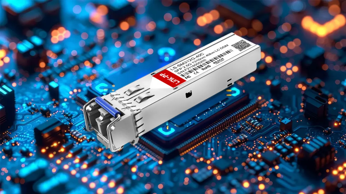
An SFP (Small Form-Factor Pluggable) transceiver is a hot-swappable network module that converts electrical signals from switches or routers into optical or copper signals for data transmission. Engineers use SFPs to flexibly deploy 1G to 10G links over copper or fiber, optimizing port density, power consumption, and upgradeability in enterprise, data center, and telecom networks.In practice, SFP transceivers are preferred over fixed ports because they decouple switch hardware from media choice, allowing independent upgrades of speed, reach, and fiber type.
The Evolution of SFP Technology
SFP (Small Form-Factor Pluggable) transceivers fundamentally reshaped network architecture by replacing bulky, power-hungry GBICs with compact, hot-swappable optical and copper modules. Defined under the Multi-Source Agreement (MSA), SFPs enabled multi-vendor interoperability, higher port density, and faster lifecycle upgrades. Today, SFP, SFP+, and QSFP families underpin everything from enterprise access layers to hyperscale data centers, 5G fronthaul/backhaul, and AI fabrics—where density, power efficiency, and deterministic performance are no longer optional but mandatory.
Quick Comparison: SFP vs SFP+ vs QSFP
SFP, SFP+, and QSFP differ primarily in bandwidth, power consumption, and deployment layer. SFP supports 1G access links with low power draw, SFP+ enables 10G connectivity for ToR and aggregation layers, while QSFP aggregates multiple lanes to deliver 40G/100G+ bandwidth in spine and AI fabrics where density outweighs power cost.In short, SFP prioritizes efficiency, SFP+ balances speed and density, and QSFP maximizes aggregate bandwidth at the cost of power.
Core Technical Specifications & SFP Form Factors
Electrical, Optical, and Thermal Fundamentals
- Electrical Interface: 3.3V ±5% supply (VCCT/VCCR), differential signaling with 100Ω impedance, AC-coupled TX/RX lanes. Poor impedance matching is a common root cause of intermittent CRC errors.
- Power Envelope: Classic SFP <1W, SFP+ typically 1–1.5W, copper SFP up to 2.5W. Power directly correlates with thermal stress and long-term MTBF.
- Thermal Constraints: In high-density ToR switches, sustained inlet temperatures above 55°C can push marginal optics into thermal throttling or silent error states.
SFP, SFP+, QSFP Decision Matrix (Engineer-Oriented)
| Form Factor | Speed | Typical Power | Port Density | When It Fails |
|---|---|---|---|---|
| SFP | 1G | ~0.8W | Medium | Future upgrades ignored |
| SFP+ | 10G | 1–1.5W | High | Inadequate airflow |
| QSFP28 | 100G | 3.5–5W | Very High | Overkill at access layer |
Engineering Rule: Use SFP for stable 1G access, SFP+ for ToR/Leaf layers, and reserve QSFP for spine or AI workloads where bandwidth aggregation offsets power cost.
SFP Optical & Copper Module Types
| Type | Speed | Medium | Reach | Primary Use Case |
|---|---|---|---|---|
| 1000BASE-T | 1G | Cat5e/6 | 100m | Legacy campus, low port count |
| 1000BASE-SX / 10G SR | 1G/10G | MMF OM3/OM4 | 300–550m | Intra-DC links |
| 1000BASE-LX / 10G LR | 1G/10G | SMF | 10–20km | DCI, enterprise backbone |
| ZR / ZR+ | 10G+ | SMF | 80–120km | Metro & telecom aggregation |
How to Calculate Optical Power Budget (Production-Proven)
Optical Budget Formula:
Optical Budget = Tx Power (min) – Rx Sensitivity – Total Link Loss
10G LR Example (10 km):
- Tx Min: −8.2 dBm
- Rx Sensitivity: −14.4 dBm
- Available Budget: 6.2 dB
- Fiber Loss: 0.4 dB/km × 10 km = 4 dB
- Connector Loss: 0.5 dB × 2 = 1 dB
Result: Remaining margin ≈ 1.2 dB — acceptable but tight. Any contamination or bend loss will push the link into LOS.
Compatibility Reality: MSA vs Vendor Lock-In
Although MSA defines mechanical and electrical standards, major OEMs often enforce firmware-level transceiver authentication. Cisco, Juniper, and Arista platforms may partially accept third-party modules but silently degrade performance.
- Risk: “Link up, traffic unstable” scenarios.
- Mitigation: Use EEPROM-matched, MSA-certified optics from validated suppliers such as Link-PP.
Actual behavior varies by platform model and software version.
Five Non-Negotiable Compatibility Checks
- Exact wavelength and fiber type alignment.
- Switch OS and firmware support.
- DDM/DOM availability.
- No CWDM/DWDM mixing without mux.
- BER ≤ 1E-12 under sustained load.
Real-World Failure Scenarios (Field Experience)
Case 1: Copper SFPs in High-Density Switches
RJ45 SFPs routinely exceed 2.5W, overwhelming ToR thermal design. Result: random link flaps after 48–72 hours.
Solution: Replace with SR optics or DACs.
Case 2: Third-Party SFPs Passing Detection but Failing Traffic
EEPROM passes vendor check, but DOM alarms misreport optical levels. Result: high BER despite clean link state.
Solution: Always validate with traffic generators and long-duration soak tests.
Why DDM Is Mandatory in Modern Networks
DDM (SFF-8472) enables real-time visibility into temperature, voltage, TX/RX optical power. In large-scale deployments, DDM is the only scalable Layer‑1 observability tool.
- Early detection of fiber degradation
- Root cause isolation (connector vs optic)
- Predictive maintenance capability
Application Scenarios & Practical Selection Examples
A. High-Impact Use Cases
- Copper SFP: Cost-effective switch-to-server links in edge networks.
- Long-Haul Fiber: 120km ZR modules with APD receivers for metro networks.
- QSFP Breakouts: 1x100G to 4x25G for scalable spine-leaf architectures.
B. Selection Algorithm

C. Technology Drivers Behind Next-Gen SFP and QSFP Modules
- LPO (Linear Pluggable Optics): Replaces DSP with analog circuits, cutting 10G SFP+ power by 50% (NVIDIA AI deployments).
- 800G Modules: 7nm DSP (Broadcom) vs. silicon photonics (Intel)—battling for AI/ML supremacy.
Future Trends: LPO, Silicon Photonics, and 800G
- LPO: Eliminates DSP, reducing power by up to 50% in AI clusters.
- Silicon Photonics: Higher integration, lower BOM, but tighter thermal margins.
- 800G Optics: Becoming the new spine standard for hyperscale AI fabrics.
SFP Deployment Rules (Snippet-Optimized Checklist)
The following deployment rules summarize the most common causes of SFP instability in production networks:
- Always match wavelength and fiber type. SR modules require MMF, while LR/ZR require SMF; mismatches cause immediate attenuation loss.
- Validate optical power budget before install. Links with <1 dB margin are unstable in production environments.
- Avoid high-density copper SFP deployments. RJ45 SFPs exceed thermal design limits in most ToR switches.
- Prefer DDM-enabled transceivers. Without DOM data, large-scale fault isolation is impossible.
- Run BER and soak tests. A clean link state does not guarantee acceptable error rates.
FAQ
Can SFP+ modules operate in SFP ports?
No. SFP+ optical modules require higher-speed electrical interfaces and signal integrity characteristics that are not supported by standard SFP ports.
How can vendor lock-in be avoided when deploying optical transceivers?
Vendor lock-in can be avoided by deploying MSA-compliant transceivers with properly matched EEPROM coding and documented platform validation, ensuring interoperability across multiple switch vendors.
What typically triggers Loss of Signal (LOS) alarms?
Loss of Signal (LOS) alarms are typically triggered when the received optical power falls below the receiver sensitivity threshold, often due to dirty connectors, fiber damage, or excessive link attenuation.
Conclusion: Engineering for Stability, Not Just Link-Up
SFP transceivers remain foundational to scalable networks. Long-term stability depends less on brand and more on optical budget discipline, thermal awareness, and real validation. In production, always prioritize DDM-enabled, thermally efficient, MSA-compliant modules.
Pro Tip: For industrial or outdoor deployments, select extended-temperature (-40°C to 85°C) SFPs such as Link-PP industrial-grade transceivers to prevent cold-start and heat-induced failures.
Tags:

-
Nav Menu
-
About LINK-PP
-
All Products
-
Applications