


10G BiDi SFP+ 40 km Guide: Wavelength Pairing and Link Budget

LINK-PP Official ·


Introduction: Why Choose a 10G BiDi SFP+ for a 40 km Link?
A 10G BiDi SFP+ transceiver designed for a 40 km reach can transmit and receive over one strand of single-mode fiber. Compared with a conventional duplex optical link, this frees one fiber strand for another connection.
This can be useful when a campus, metro network, or remote site has limited spare fiber. The actual saving depends on the available route, transceiver cost, patching, and whether new fiber installation can be avoided.
A “40 km” label is a reach designation, not a guarantee that every fiber route under 40 km will work. Before ordering, check the wavelength pair, host compatibility, fiber loss, optical budget, and receiver input range in both directions.
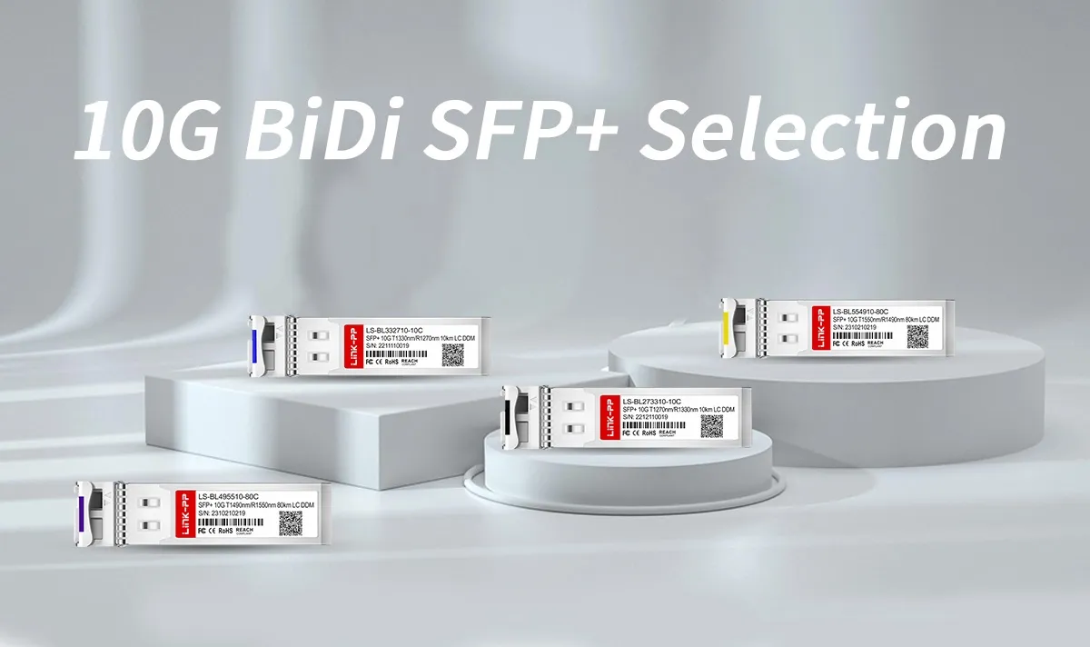
This guide focuses on selecting and deploying 10G BiDi SFP+ modules with a 40 km reach designation. For a broader explanation of BiDi technology, see the BiDi SFP and single-fiber networking guide.
How Does a 10G BiDi SFP+ 40 km Link Work?
A single-fiber BiDi link uses different wavelengths to carry signals in opposite directions. An optical WDM component in each transceiver separates the outgoing and incoming signals.
For a 1270 nm / 1330 nm implementation:
- End A: TX 1270 nm / RX 1330 nm.
- End B: TX 1330 nm / RX 1270 nm.
Each transmitter must operate within the remote receiver’s specified wavelength range. The two modules must also support compatible rates, protocols, optical power levels, and host equipment.
This wavelength pair is an example used by some 10G BiDi products; it is not the only possible BiDi wavelength combination. For more information about fiber paths and WDM arrangements, read the single-fiber vs. dual-fiber WDM architecture guide.
10G BiDi SFP+ 40 km: Wavelength Pairing
When selecting a pair, compare the TX and RX labels at both ends. A module transmitting at 1270 nm normally needs a remote receiver specified for 1270 nm, while the remote transmitter must be within the first module’s 1330 nm receive range.
| Link End | Transmit Wavelength | Receive Wavelength | What to Verify |
|---|---|---|---|
| End A | 1270 nm | 1330 nm | Remote receiver accepts End A’s transmitter wavelength |
| End B | 1330 nm | 1270 nm | Remote receiver accepts End B’s transmitter wavelength |
Nominal wavelength labels are a useful first check. Final selection requires the full wavelength ranges and optical specifications from both module datasheets.
Two modules with the same TX/RX orientation do not normally form a compatible single-fiber point-to-point pair. For example, two modules labeled TX 1270 nm / RX 1330 nm would each transmit at 1270 nm while expecting to receive at 1330 nm.
LINK-PP 10G BiDi SFP+ Product Selection
The table below identifies LINK-PP products from the available product listings. Reach designations describe individual products and do not replace an optical budget or host compatibility check.
| LINK-PP Model | Reach Designation | Nominal TX / RX | Selection Note |
|---|---|---|---|
| LS-BL273310-10C | 10 km | 1270 nm / 1330 nm | 10 km product; do not substitute its reach designation for a 40 km link requirement. |
| LS-BL332710-40C | 40 km | 1330 nm / 1270 nm | Check the approved datasheet, host coding, and complementary module before ordering. |
| LS-BL495510-80I | 80 km | 1490 nm / 1550 nm | Longer-reach product with a different wavelength orientation; requires its own compatible counterpart and optical checks. |
The 10 km and 80 km models are included for comparison. They are not automatically interchangeable with the 40 km module, and the 80 km 1490 nm / 1550 nm module is not a wavelength counterpart for a 1270 nm / 1330 nm module.
LINK-PP also lists the LS-BL273310-40C with a 40 km reach designation and TX 1270 nm / RX 1330 nm wavelength orientation. Its nominal wavelengths complement those of the LS-BL332710-40C listed above. Before treating the two as an approved pair, confirm their current datasheets, optical specifications, host coding, and equipment compatibility with LINK-PP.
Operating Temperature and DOM
Check the operating case-temperature range and digital diagnostic monitoring support for the exact part number. A commercial-temperature module should not be assumed to have the same rating as an industrial version simply because the wavelength and reach are similar.
DOM availability and the values displayed by the host depend on the module and equipment. Refer to the approved product documentation for the applicable functions and limits.
How to Select a 10G BiDi SFP+ 40 km Pair
1. Confirm the Host Ports and Protocol
Record the switch, router, or media converter model at both ends, together with the port type, software version, and required 10G application.
The module must fit the port and be supported by the host. Compatibility can depend on the exact module coding, equipment model, and software release. Confirm the intended configuration before ordering.
2. Check Both Wavelength Directions
Verify the transmitter and receiver wavelength ranges at both ends. Do not rely only on “U/D,” “A/B,” or pull-tab color. These labels can help identify a part, but the actual TX/RX specification is the basis for pairing.
3. Confirm the Fiber and Connector
A 40 km single-fiber BiDi module is generally selected for a suitable single-mode fiber path. Verify the fiber type and optical connector in the module datasheet, as well as the installed route and patch-cord interfaces.
For background on single-mode cable selection, see the OS1 vs. OS2 single-mode fiber comparison. The cable’s specifications and installation conditions must be considered alongside the transceiver requirements.
Check connector polish as well as connector shape. For example, APC and UPC connectors should not be mated directly.
4. Calculate the Optical Budget in Both Directions
A 40 km designation does not mean that every 40 km BiDi transceiver has the same optical budget. Use the minimum transmitter output and the remote receiver sensitivity specified for the two selected modules.
Optical power budget (dB) = minimum transmitter output power (dBm) − remote receiver sensitivity (dBm)
Compare that budget with the total optical path loss at the relevant wavelength. Include fiber attenuation, connectors, splices, patch panels, and other optical components, then retain a margin suitable for the design.
Repeat the calculation from the opposite end. The two directions use different wavelengths and may have different transmitter, receiver, and path-loss values.
Illustrative Budget Calculation
| Parameter | Example Value |
|---|---|
| Minimum transmitter output | −3 dBm |
| Remote receiver sensitivity | −18 dBm |
| Basic power budget | 15 dB |
| Estimated total path loss | 12 dB |
| Remaining margin | 3 dB |
In this example, the basic budget is 15 dB and the remaining margin after 12 dB of path loss is 3 dB. These are illustrative values, not specifications for a LINK-PP product. Whether the margin is sufficient depends on the design requirements and assumptions.
5. Check Receiver Overload on Short Links
A 40 km transceiver may also be used on a shorter path, but the signal must not exceed the remote receiver’s maximum input power. For each direction, compare:
Maximum transmitter output (dBm) − minimum path loss (dB) ≤ remote receiver maximum input power (dBm)
If attenuation is required, select it according to the actual module and link specifications. Check the attenuator’s loss at both operating wavelengths and confirm that the resulting receive power remains within range in both directions. A fixed attenuation value should not be assumed for every 40 km link.
Deployment and Maintenance Best Practices
Label Both Ends of the Link
Record the module part number, TX wavelength, RX wavelength, host port, and fiber route. A label such as “TX 1270 / RX 1330” is more informative than relying on “Side A” alone.
Inspect and Clean Connectors
Inspect and clean connectors using the procedures and tools appropriate for the connector type. Check all patch points in the optical path, not only the transceiver interface.
Respect the Cable Bend Radius
Follow the installed fiber cable and patch-cord manufacturers’ minimum bend radius specifications. Limits can differ between cable types and between installation and long-term operating conditions.
Measure End-to-End Insertion Loss
Use a suitable optical light source and power meter with an applicable test method. Characterize the path at wavelengths appropriate to the two BiDi directions and record the reference method used.
An optical time-domain reflectometer (OTDR) can help locate fiber events, splices, or faults. It does not automatically replace an end-to-end insertion-loss measurement.
Review DOM and Host Counters
Where supported, compare transmitter power, receiver power, temperature, and alarms against the module’s specified limits. Review port errors and equipment logs alongside the optical readings.
DOM readings have product-specific accuracy and calibration limits. A reading near a threshold should be evaluated with that uncertainty in mind.
Follow the equipment manufacturer’s laser safety procedures. Do not look into an optical connector or fiber end, and verify that a fiber is safe to inspect or test.
Where Are 10G BiDi SFP+ 40 km Modules Used?
- Metro Ethernet: Point-to-point access or aggregation links where a suitable single-mode fiber strand is available.
- Campus and enterprise networks: Links between buildings or remote facilities when the fiber route and equipment support the selected modules.
- Service provider networks: Access and backhaul links where conserving fiber strands has operational value.
- Data center interconnects: Connections between sites when the required interface, distance, fiber characteristics, and optical budget fit the module specification.
In each case, the network design must account for the actual route loss, fiber characteristics, environmental conditions, and equipment support.
10G BiDi 40 km Troubleshooting
| Symptom | Checks to Start With |
|---|---|
| Link does not come up | Verify module recognition, host support, speed, protocol, fiber continuity, and complementary TX/RX wavelengths. |
| Low receive power at one end | Check the remote transmitter, connector cleanliness, path loss, and receiver sensitivity for that direction. |
| Receive power is above the specified limit | Compare maximum transmitter output and minimum path loss with the remote receiver’s overload limit. Assess attenuation if needed. |
| Link is up but errors increase | Review DOM readings, port counters, logs, connector condition, and optical margin. Use additional tests to isolate the cause. |
Frequently Asked Questions
Can I connect a 10G BiDi SFP+ to a standard duplex SFP+?
Do not assume a direct connection will work. A conventional duplex SFP+ normally uses separate fibers for transmission and reception. A single-fiber BiDi link requires a compatible optical interface at the other end or an explicitly supported conversion arrangement.
Can two 1270 nm TX / 1330 nm RX modules work together?
Not as a typical complementary single-fiber point-to-point pair. Each module transmits at 1270 nm but expects incoming light in the 1330 nm receive range. Select a compatible opposite orientation and verify the complete specifications.
Does a 40 km rating guarantee operation over any 40 km fiber?
No. The installed path must meet the module’s optical and fiber requirements. Fiber attenuation, connectors, splices, other components, and engineering margin all affect whether the link is within budget.
Can I use a 40 km BiDi module on a short fiber link?
It may be possible, but check that the received power does not exceed the remote receiver’s maximum input limit in either direction. Add suitable attenuation only if the calculations or measurements and product specifications show that it is required.
Is a 10 km BiDi module compatible with a 40 km BiDi module?
Reach labels alone do not establish compatibility. The two modules must have compatible wavelengths, rates, protocols, host support, and optical power levels in both directions. The actual fiber path must fit the resulting link budget.
Can I identify the wavelength by pull-tab color?
Pull-tab colors may help when the supplier documents their meaning, but colors should not be treated as a universal wavelength standard. Check the part number, module label, and product documentation.
Do both ends of a 10G BiDi link need to support DOM?
DOM is not what carries the optical traffic, so it is not a universal requirement for link operation. When supported by the modules and hosts, it can help monitor optical and environmental parameters at each end.
Conclusion
A 10G BiDi SFP+ pair with a 40 km reach designation can provide a single-fiber link when the selected modules and installed path meet the application requirements.
Start with the host equipment and complementary wavelengths. Then check the fiber interface, total loss, optical budget, and receiver input limits in both directions. For product selection, prepare the equipment models, software versions, required data rate, fiber type, route length, and any available loss measurements.
Explore the LINK-PP 10G SFP+ transceiver range or contact LINK-PP to confirm the appropriate wavelength pair and host compatibility for your project.
Related Technical Reading
- BiDi SFP and Single-Fiber Networking Guide
- Single-Fiber vs. Dual-Fiber WDM Architecture
- OS1 vs. OS2 Single-Mode Fiber
Technical References
Tags:

-
Nav Menu
-
About LINK-PP
-
All Products
-
Applications